IEEE FOOTHILL SUPPORTS IEEE CLASTECH 2015—ALL-DAY RF TOPICS
| January 12, 2016 | Posted by Frank Gomez under CN, COMSOC, EDCAS, MTT/APS |
Comments off
|
CLASTECH_REPORT
(1) Presentation on “End-to-End Antenna and Feed Network Design using Hybrid Methods” by
Ralf Ihmels ( Mician)
As expected, the current emphasis is to use microwave (MW) software for design of passive components. For verification of the software solution, it is necessary to check these predictions, in selected critical cases, in the lab with Vector Network Analyzer (VNA) instrumentation. Current MV designers, as well as their reporting program managers, want to avoid resorting to using tuning screws, etc, on built hardware to meet specifications. Currently, software chains are used to model interactions between components from MW power source / modulator to transmitting antenna.
It was noted that many software techniques available, and multiple of commercial packages for each technique. In Dr Ihmels ‘ experience and considered opinion, all are good but some are more suitable for different passive component designs than others.
A listing of software techniques was provided, which included for our discussion: MM (mode matching); FDTD (finite difference time domain); MoM (Method of Moments); and FEM (finite element methods) for both 2D and 3D applications.
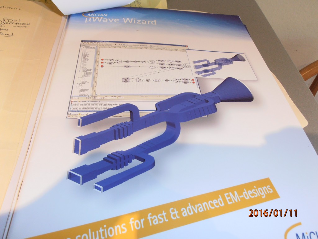
Dr Ihmels walked us through a typical example of the situation that a MW designer encounters. The design called for a composite waveguide (WG) with two 90 Deg bends/ flanges on each end; these were part of a 10 dB directional coupler. First up for use was a 3D FEM program. This program predicted smooth response, as could be measured by the predicted S-parameters. However, lab VNA tests showed spurs in the 14 to 15 Ghz range for this coupler. Why?
(It should be noted that Dr Ihmels reported that later analysis, using the same 3D FEM software program, using a modified hardware design with longer flanges on the 90 Deg bend arms, the spurs were found. So the MW designer has sensitivity issues in his design. Beware, remember this example, and use suitable caution in future designs of passive components.)
What were the investigative steps that Dr Ihmels used? Firstly, retaining the 3D FEM software, he changed the frequency sweep / step size to 0.1 Mhz , much finer that the original analysis where this was set at 1.0 MHz. This attempt found the spurs but needed 160 min on a Dell Neon 64 bit PC. Hence, this analysis method was considered too slow.
Secondly, he used a hybrid solver with MM and 2D FEM software. This approach identified the spurs, but it required 12.5 minutes of PC time.
Thirdly, he used the same hybrid solver, but set it up with a 3D FEM and ordered basis functions. This found the spurs; the required PC (CPU) running time decreased to 8 minutes.
A note on the hybrid solver method of setting up the model for this device was described by our presenter. The directional coupler was modeled as two separate WGs, with the iris connecting them. The iris was modeled as a discrete transmission line. Then all modes were calculated. Then either use a mesh based solver (FEM, MoM, or FDTD); alternatively use a mode matching solver and calculate all eigenmodes, including the effervescent modes.
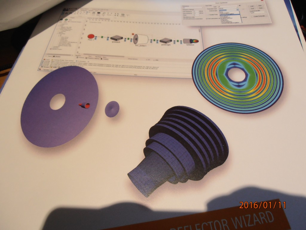
A more extensive example discussed was the design of a compact axial /vertical corrugated horn antenna. Specifications were given for such parameters as: operating frequency of 10 to 12 GHz, gain, edge taper, XPol (cross-polarization) less than -30dB , out to a goal of -40 dB; and return loss. First to get a flat field (near Gaussian) at the horn aperture, mode conversion was made (85 % TE11 plus 15 % TM11 to yield HE11). Then an optimization analysis must be done to size the depth of the axial corrugations, up to a maximum depth of lamba /4 . EM analysis here is done by MM and spherical wave eigenmodes, using the symmetry of the horn.
Other technical examples were covered to show how physical complexity and symmetry drive the selection of the software that would be used.
The summary message by our speaker today: all electromagnetic (EM) software packages are good, but they must be used with knowledge of both their strong and their weak points (including CPU time needed for convergence) and with knowledge of the EM specifications for the component to be designed. What software is most adaptable for your design problem? This is a question every MW designer needs to address at the beginning of a project.
These electromagnetic (EM) software skills mean acquiring hands-on experience. Be sure to use this information when the next EM software representative knocks on the door of your shop.
(2) Presentation on “5G Wireless Trends and Millimeter Technical Overview” by Ms Debabini Choudhruy of Intel
Just what is 5G wireless communication? Our speaker did not attempt to answer that question. It would have meant a strenuous voyage through the IEEE 802.11 standards group. It would have meant stopping at every version of the 802.11specification that is either accepted, under review, already promulgated, or still in the design and IEEE standards board discussion stage, from 802.11a to the in-process 802.11 ax,-ay, and –az. It would have meant a week long discussion of the various MAC (media access control) and PHY (physical layer) models and requirements. Better yet, since the 5G standard is some 4 to 5 years away, it would have been merely a guessing game.
Instead, our speaker introduced some of the driving factors that are influencing thinking about 5G. These include: the Internet of Things, E-Health Net, Autonomous vehicles, QoE (quality of Experience). These are potential uses and users contributing to a current annual 20 to 25 % data rate growth.
What will the technical trade-offs be before a draft 5G standard is posted for review and public user commentary? The issues for confronting 5G can be summarized as: densification of devices; ubiquitous connectivity; throughput capacity; very low latency (aim for 1msec), and content delivery.
The consideration of millimeter wave frequencies (60 Ghz and above) is driven by the higher potential bandwidths (BW) that could be available, plus the fact that these frequency bands may be legally available. Multiple-input-multiple-output (MIMO) antennas with beamforming would be needed for beam-steering from a base station to a user. Think power and signal to noise ratios; 360 degree coverage, with azimuthal and elevation beam-steering. Not surprising, the top-level problems for millimeter wave frequencies are signal overhead, complexity, cost and efficiency.
Yes, there are many technical breakthroughs that are needed before we have a specification for 5G. These were further addressed in the day-long IEEE 5G Summit Silicon Valley held in Santa Clara on November 16, 2015. We thank our speaker today for a gentle introduction to this fascinating world of 5G wireless.
(3) Presentation on “Dynamics, Bifurcation, and Practical stability Analysis / Design of Non-Linear Microwave Circuits and Networks” by Professor Almudena Suarez ( University of Cantabria, Spain) and Christopher P. Silva (Aerospace Corporation)
It is always useful for working EEs to return to a basic problem; namely, design an amplifier that will not have any oscillations under any operating conditions. Since amplifiers are non-linear devices, we know that there are hysteresis effects, coupling effects and potential subharmonic mixing modes that can excite “near-chaotic” (in phase space) modes of operation.
The first part of this talk covered some basic ideas for non-linear models: ordinary differential equations (time, position variables) which contain non-linear terms, and their resulting unique time-dependent phase space curves; strange attractor theory; and Lyapunov stability and control rules.
Then we examined the use of stability analyses for a real microwave circuit problem. This involved looking at a high power class E/F amplifier (nominally for space / satellite applications). In this case, increasing the input power first showed the expected frequency spectrum together with low power leakage. Increasing the input power further caused a chaotic spectrum. Changing the DC bias for the drain on the (LDMOS) power transistors showed a spectrum with many mixed terms for the input frequency and the unwanted oscillation frequency. This oscillation frequency could be analytically identified with the bifurcation crossover on the real / imaginary frequency plane.
The analyses procedure was only summarized. This involved linearization of the power amplifier circuit in the large signal region; characterization of the circuit at numerous harmonic components; and determination of the admittance for the entire circuit. For certain combinations of the input power and transistor DC bias voltages, the admittance poles migrated into the right hand side of the admittance plane. Then oscillation occurred. Lab results confirmed this behavior. Subsequently, circuit modifications were made that ensured global stability of the power amplifier with small degradation of amplifier performance. The reference given for this work was S. Jeon, A. Suarez, and David Rutledge (of Cal Tech Microwave Group) IEEE Transaction MTT, v53, 3712-3722, December 2005. This is an IEEE report deserving of further study.
We thank our speakers for their insightful discussions of their topics. It is useful to have a reminder not only of the analyses needed before brassboard / prototype microwave circuits are constructed, but of the technical depth of optimizations needed. Higher frequency circuits continue to provide surprises for EEs.
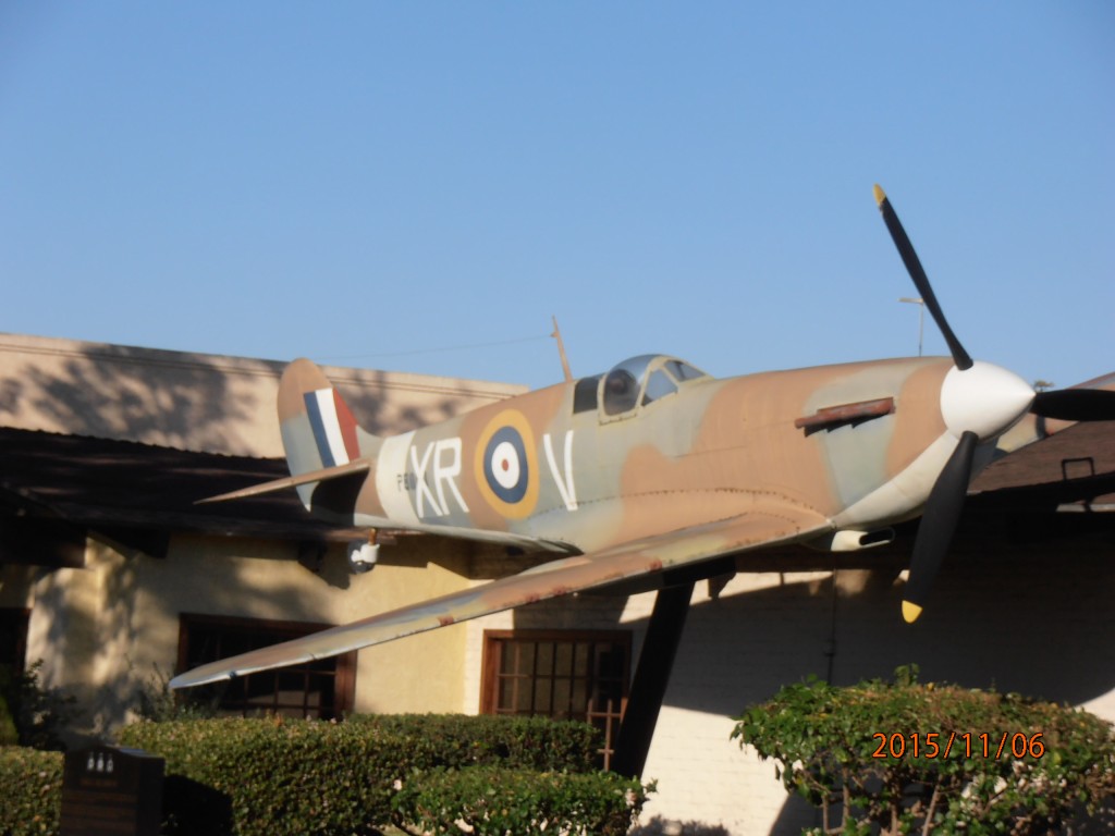
A further note on the venue for this meeting. It was held at the “Proud Bird” aviation-themed restaurant / meeting center near LAX. By petition, it was saved from the wrecking ball that is in progress in the remaking the LAX area as a major industrial area. One advantage is the many WW II vintage and later airplanes can still be seen mounted on the grounds outside the building. Just looking at their size, and remembering their flight capability, easily noted as the commercial airplanes fly almost directly overhead on their final approach glide into one of the LAX runways, one is reminded in the very recent advances in aviation, and electronics at all frequencies.


